Functional 3D printing is the discipline of printing parts that have a job to do — brackets, fixtures, enclosures, gears, hinges — rather than models that just sit on a shelf. The single biggest strength variable is print orientation: a part loaded along its layer lines can be three to five times weaker than the same part oriented so the load runs through solid plastic.
I have been printing working parts in my Sweden workshop for years — hydroponic reservoir lids, sensor mounts, welder shop fixtures, leather edge slickers, planter inserts — far more than display models. This functional 3D printing guide is the playbook I actually use on the bench: how to choose orientation, walls, infill, and material so a part survives the load it was designed for, and how to design fasteners, hinges, and fits that work the first time. Almost every other workshop hobby I run feeds a part back to this printer, so the stakes are real: a snapped bracket means a leaking reservoir or a fixture that lets a workpiece slip.
What “Functional” Actually Means
A functional part is one where dimensional accuracy, mechanical strength, or fit determines whether it works. If it bolts to something, holds a load, snaps together, flexes, or has to slide against another part, it is functional. The standard changes completely from display printing: surface finish matters less, but layer adhesion, wall count, and tolerance suddenly matter a lot.
The mistake most newcomers make is treating a functional print like a display print — same 15% gyroid infill, same default two perimeters, same arbitrary orientation that looks nice on the plate. That profile is fine for a figurine. It is wrong for a part that gets bolted to a vibrating machine. Functional printing is about matching five levers — orientation, walls, infill, material, and geometry — to the actual load case, and accepting longer print times and more plastic where strength demands it.
The Five Levers of a Strong Functional Part
Every functional print comes down to five levers, and they are not equally powerful. Orientation and wall count do most of the work; infill density is third; material and geometry round it out. Get the order wrong — cranking infill to 80% while printing the part in a weak orientation — and you waste filament and time for a part that still fails at the layer line.
Here is how the five levers compare for a typical load-bearing bracket. The ranking shifts for flexible or sliding parts, but for the most common case — a part that has to resist breaking — this is the priority order I work in.
| Lever | Strength impact | Cost (time/filament) | When it matters most |
|---|---|---|---|
| Print orientation | Very high (3–5x) | Free | Always — the first decision |
| Wall / perimeter count | High | Low | Thin-walled or impact parts |
| Infill density & pattern | Medium | Medium | Bulky parts under compression |
| Material choice | High | Varies | Heat, UV, or fatigue exposure |
| Geometry / fillets | High | Free (design time) | Stress concentrations, corners |
Print Orientation Is the Biggest Lever You Have
FDM parts are anisotropic — strong in the X and Y plane, weak in Z where layers are bonded by partial remelting rather than continuous extrusion. Protolabs Network’s FDM design guidelines quantify this orientation effect and how to design around it. In my test logs a PETG tensile bar pulled along the layers fails far below one printed so the pull runs across solid extrusions. The practical rule: orient the part so the main load runs within a layer, never across the layer stack.
A printed hook should lie down so its curve is in the build plane, not stand up where the load peels the layers apart. A bracket with a cantilevered arm should have that arm flat to the bed. Sometimes the strong orientation needs supports or sacrifices surface finish — that is the trade, and for a functional part strength wins. When orientation and pattern both matter, I cover the full decision in the dedicated guide to the strongest infill pattern and orientation.
Walls Do More Than Infill
If I could only change one slicer setting for strength, it would be perimeter count, not infill. Walls are continuous extrusions wrapping the part’s outer shell; they carry bending and torsional loads far better than the lattice inside. For a structural part I run four to six perimeters before I touch infill density. On the printers I run, going from two walls to four often does more for stiffness than doubling infill from 20% to 40%, and it uses less plastic and time.
Infill still matters for bulky parts under compression and for giving the top layers something to bridge onto. But treat it as the third lever, not the first. For thin functional parts — clips, brackets, mounts — the part can be nearly all perimeters with a token 15% infill and still be stronger than a thin-walled, high-infill version. The full design-side reasoning is in my guide to designing for strength in 3D prints.
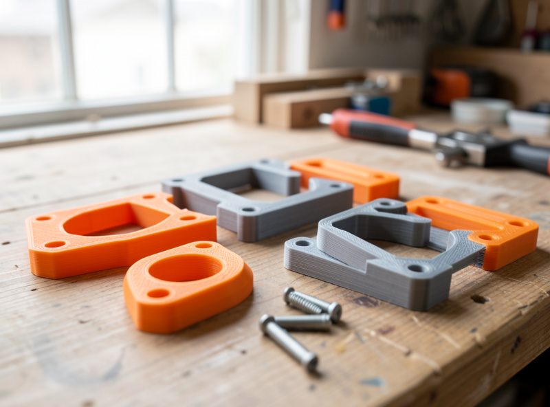
Fasteners and Assembly: Inserts, Snap Fits, Press Fits
Functional parts rarely stand alone — they bolt, clip, or press into something. How you join them decides whether the assembly survives repeated use. Threading a screw directly into printed plastic works once or twice, then strips. For anything that gets disassembled, I use brass heat-set inserts melted into the print with the soldering iron; they give a metal thread that survives dozens of cycles. The complete method — hole sizing, iron temperature, seating technique — is in my heat-set threaded inserts guide.
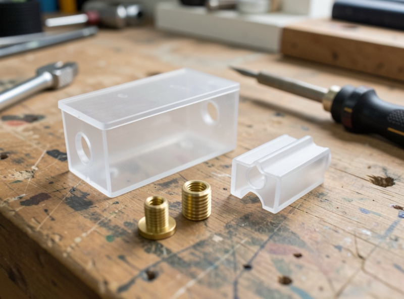
For tool-free assembly, snap fits and press fits are the workhorses. A cantilever snap clip lets an enclosure close and reopen; a press fit holds a bearing or dowel by friction alone. Both live or die on clearance — too tight and the part splits, too loose and it rattles. I walk through the geometry, the deflection math, and the material choices in the snap fits and press fits guide. Get the fastening strategy right at the design stage and the rest of the print becomes far more forgiving.
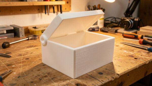
Moving Parts: Living Hinges and Print-in-Place Joints
One of the things that makes 3D printing genuinely magic for functional work is printing mechanisms that move straight off the bed. A living hinge — a thin web of plastic that flexes — lets a box lid open and close thousands of times when the material and geometry are right. PP and PETG handle the fatigue far better than brittle PLA; the web thickness and orientation are everything. I cover the working numbers in the living hinges guide.
Print-in-place parts go further: hinges, gears, and ball joints printed pre-assembled with a designed gap between moving surfaces so they never fuse. The whole trick is clearance tuned to your printer’s real tolerance. When I get the gap right on my machines, the part comes off the bed already articulating. The full approach to gaps, orientation, and first-layer squish for these is in the print-in-place hinges and joints guide.
Dimensional Accuracy and Tolerances
Functional parts that mate with other parts — or with hardware like bearings, magnets, and threaded rod — need predictable dimensions. The catch is that FDM does not print holes and slots at their modelled size: extrusion width, elephant’s foot, and shrinkage all conspire to make holes come out undersized and outer dimensions slightly oversized. On my bench a 5 mm hole modelled at nominal typically prints a few tenths small. Protolabs Network’s guide to dimensional accuracy breaks down why holes and outer dimensions drift on FDM.
The fix is a calibrated clearance you apply by feel of fit class: a few tenths of a millimetre for a tight press, more for a free-sliding fit. I keep a printed tolerance test on the shelf for each material and re-run it when I change filament brands. The complete clearance chart and how to dial it in for your own machine is in the tolerances and clearances guide. Accuracy starts upstream too — a well-tuned machine prints to size, so a clean calibration sequence pays off on every functional print.
Material Selection for Functional Parts
Material is a high-impact lever, but only when matched to the part’s environment. PLA is stiff and easy but creeps under sustained load and softens in a hot car or near a heat source — fine for indoor jigs, wrong for anything thermal. PETG is my default functional material: tough, slightly flexible, good layer adhesion, and it shrugs off moisture better than ABS in a humid Swedish workshop. ABS and ASA handle heat and, in ASA’s case, years of UV outdoors. TPU prints flexible parts like gaskets and bushings, and carbon-fibre blends add stiffness for fixtures that must not flex.
| Material | Best functional use | Strength | Heat resistance | Watch out for |
|---|---|---|---|---|
| PLA / PLA+ | Indoor jigs, low-load brackets | Stiff, brittle | Low (~55°C) | Creep, heat softening |
| PETG | General functional default | Tough | Medium (~75°C) | Stringing, needs dry filament |
| ABS / ASA | Heat & outdoor (ASA for UV) | Tough, impact-ready | High (~95°C) | Warping, needs enclosure |
| TPU 95A | Gaskets, bushings, flex parts | Flexible, tough | Medium | Slow prints, retraction |
| PA-CF / PETG-CF | Stiff fixtures, brackets | Very stiff | High | Abrasive, hardened nozzle |
If you are still building your filament shelf, my filament guide covers the full lineup, and the carbon fibre filament guide explains where the stiff blends earn their cost. For flexible functional parts, the TPU settings profile is what I actually run. For outdoor parts, the ASA vs ABS weather test shows why ASA wins in sunlight.
My Functional-Print Workflow, Start to Finish
The way I dial mine in is a repeatable loop. First, define the load case in plain words — “this bracket holds a 2 kg pump and gets bumped.” Second, design with strength in mind: fillet the corners, add ribs instead of bulk, size holes for the fastener strategy. Third, orient for strength in the slicer before anything else, then set walls, then infill. Fourth, choose material for the environment, not habit. Fifth, print a quick test of any critical fit before committing to the full part.
Finishing is the last step and it is functional too: deburring a press-fit hole, cleaning supports off a mating face, and reaming an insert hole all change whether the part assembles. I cover clean support removal in the support removal guide. And when a part needs tighter accuracy or far higher strength than FDM can give, I prototype on the printer and move to the mill — the 3D-print-to-CNC hybrid workflow is how I bridge the two. The printer is the connective tissue of the whole workshop — almost every other project has a part that came off this bed.
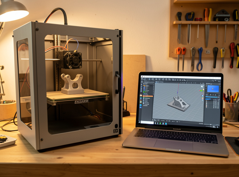
For the machines themselves, my Prusa MK4S review explains why it is my reliability benchmark for functional work, and the best 3D printer guide sorts the field by use case. A reliable machine that prints to size is the foundation everything else here is built on.
Slicer Settings I Start From for Functional Parts
There is no universal functional profile, but there is a sensible starting point I load before I tune for the specific part. Walls come first: four perimeters for anything that bends or carries load, six for impact parts like clips and hold-downs. Top and bottom layers get five or six solid layers so the surfaces are continuous rather than bridging over sparse infill — thin top shells are a common hidden weakness on functional parts that otherwise look solid.
Infill I start at 25% with a gyroid or grid pattern for general parts, dropping to 15% on thin wall-dominated parts and climbing to 40–50% only on bulky parts that take compression. Layer height is a strength lever people forget: thinner layers bond better and carry load better, so I drop to 0.15 mm for critical functional parts and accept the longer print, while 0.2 mm is fine for general work. Print temperature gets nudged toward the top of the material’s range, because hotter plastic fuses layers more completely — layer adhesion is a temperature game as much as a settings game.
Two settings I deliberately slow down are the outer wall speed and the cooling on the first few layers. A slower outer wall lays a cleaner, better-bonded perimeter, and easing off the part-cooling fan on tall thin functional parts in PETG or ABS keeps the layers warm enough to weld. None of this is exotic — it is the same handful of dials in PrusaSlicer or OrcaSlicer, set with strength as the goal instead of speed. A clean machine helps too: worn belts and a sloppy first layer undermine every one of these settings, which is why a periodic maintenance routine is part of functional printing, not separate from it.
Real Functional Parts From My Bench
The fastest way to understand functional printing is to look at parts that earn their keep. The reservoir lids I print for my hydroponic setup are a good example: they have to seal against light to stop algae, carry net-pot holes cut to a press fit, and survive constant humidity without warping. PLA was a disaster there — it crept and sagged over a warm summer. PETG with four perimeters has held for months. That is functional printing in one part: material chosen for the environment, walls chosen for the load, holes sized for the fit.
The sensor mounts I print for smart-home gear are the opposite end of the load scale — light parts where dimensional accuracy beats raw strength, because the bracket has to clip a specific sensor and screw to a specific stud spacing. The welder shop fixtures are the strength end: hold-downs and gauges that take knocks and heat near the bench, so they get ASA and heavy walls. And the leather edge slickers I print are about surface and shape rather than load, finished smooth so they burnish an edge cleanly. Four parts, four completely different priority stacks — that is the judgement functional printing trains.
None of these are downloads I printed unchanged. Every one started as a real workshop need, got modelled to fit the exact hardware, and went through a test print of the critical feature before the full part. That loop — need, model, test the fit, commit — is what separates a part that works from a part that looks like it should.
Common Functional-Print Failures and How I Fix Them
Most functional-print failures fall into a handful of buckets, and once you can name them they are quick to fix. Layer separation under load almost always means the part was printed in the weak orientation or with too few walls — reorient first, add perimeters second. A part that fits perfectly in CAD but not in reality is a tolerance problem: print a clearance test and apply the offset that matched the fit class you wanted, rather than rescaling the whole model.
Stripped threads mean a screw went straight into plastic where a heat-set insert belonged. Cracked snap clips mean the cantilever was too stiff for the material — a longer, thinner arm flexes instead of snapping, and PETG tolerates the strain where PLA shatters. Warping on a big functional part in ABS or ASA is an environment problem solved by an enclosure, not a slicer setting. And a part that comes out brittle weeks after printing is usually wet filament that degraded layer adhesion; dry the spool and the next print bonds properly.
The pattern across all of these is that the fix lives upstream of the symptom. The crack you see is rarely caused by the setting you are tempted to change. Naming the failure mode — orientation, walls, tolerance, fastener, material, moisture — points you at the lever that actually moves it.
The Gear That Earns Its Place
You do not need much beyond a reliable printer to do functional work, but a few cheap tools punch above their weight. A basic brass heat-set insert assortment turns flimsy plastic threads into metal ones for the price of a couple of spools, and a temperature-controlled soldering iron with insert tips seats them square instead of melting a crater. A set of digital calipers is the single most useful measuring tool on my bench — you cannot dial in tolerances you cannot measure. As an Amazon Associate I earn from qualifying purchases.
Beyond those, the things that improve functional output are not gadgets: dry filament, a tuned first layer, and a habit of test-printing the critical feature. The cheapest printer is rarely the cheapest to own once you count failed functional prints, which is the through-line of everything I write here.
Frequently Asked Questions
What infill percentage is best for functional 3D prints?
For most functional parts, 20 to 40 percent infill paired with four to six perimeters is the sweet spot. Walls carry bending loads better than infill, so increase wall count before chasing high infill density. Only bulky compression parts benefit from 50 percent or more.
Which material is strongest for functional 3D printed parts?
PETG is the best all-round functional material: tough, good layer adhesion, and forgiving. For heat or outdoor use, ASA and ABS win. Carbon-fibre blends like PA-CF give the highest stiffness for fixtures that must not flex. PLA is stiff but brittle and creeps under load.
Why do my functional prints break along the layer lines?
FDM parts are weakest in the Z direction where layers bond by partial remelting. If a load peels the layers apart, the part fails early. Reorient so the load runs within a layer rather than across the layer stack, and the same part can be three to five times stronger.
How do I add strong screw threads to a 3D printed part?
Melt brass heat-set inserts into the print with a soldering iron. They give a metal thread that survives dozens of assembly cycles, unlike screws driven straight into plastic, which strip after a few uses. Size the hole to the insert outer knurl diameter for a clean seat.
Do I need a special printer for functional parts?
No. Any well-calibrated FDM printer makes strong functional parts once it prints to size and bonds layers cleanly. Material range matters more than the machine: an enclosure helps with ABS and ASA, and a hardened nozzle is needed for abrasive carbon-fibre blends.
How much clearance should I leave for fitting parts together?
It depends on the fit class and your printer. A tight press fit needs roughly 0.1 to 0.2 mm of clearance, a sliding fit around 0.3 to 0.4 mm. Print a tolerance test for each material because brands and machines vary, then apply the gap that matched the fit you wanted.