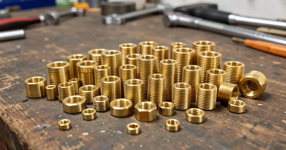
Heat-set inserts are brass threaded bushings you melt into a 3D printed part with a soldering iron, giving it a metal thread that survives repeated assembly. They are the single best upgrade for any part that gets screwed together more than once: where a screw driven straight into plastic strips after two or three cycles, a properly seated heat-set insert holds for dozens. Done right, the whole operation takes under ten seconds per insert.
I use them everywhere on functional parts — enclosure lids, sensor mounts, welder fixtures, anything that has to come apart for maintenance. The technique looks fiddly the first time and then becomes muscle memory. The two things that decide success are the hole diameter in your model and the iron temperature, and both are easy to get right once you know the numbers. This guide is the method I actually use on the bench, and it slots straight into the functional printing workflow.
Why Heat-Set Inserts Beat Screwing Into Plastic
Threads cut into printed plastic are weak in two ways. The thread itself is shallow and made of a material that deforms, and on an FDM part the thread crosses layer lines that want to split. The first few times you drive a screw it holds; then the plastic creeps, the thread rounds off, and the screw spins. For anything you will open and close — a battery box, a camera bracket, a serviceable enclosure — that is a failure waiting to happen.
A heat-set insert solves it by giving you a real machine-screw thread in brass, anchored into the plastic by a knurled, often barbed outer surface. When the brass is heated and pushed in, it melts the surrounding plastic, which then solidifies around the knurls and locks the insert in place. The result resists both pull-out and the rotational torque of tightening a screw. It is the same approach used in injection-moulded electronics housings, brought to the desktop with nothing more than a soldering iron.
Sizing the Hole: The Number That Matters Most
The hole in your model has to be slightly smaller than the insert’s largest outer diameter so there is plastic for the brass to melt into and grip. Too wide and the insert spins or drops straight through; too narrow and you displace so much plastic it bulges the part or the insert seats crooked. The right hole gives a snug start where the insert balances on the opening before you melt it home.
These are the starting hole diameters I model for the common metric inserts. Manufacturers vary slightly, so check your insert’s spec, but these get you a clean seat on the first try for most standard tapered inserts. Markforged’s heat-set insert guidance recommends a counterbored hole — wider at the top — to guide the insert and give displaced plastic a well to flow into.
| Insert thread | Insert OD (typical) | Modelled hole diameter | Min boss diameter |
|---|---|---|---|
| M2 | ~3.2 mm | 3.0 mm | 5.5 mm |
| M3 | ~4.0 mm | 3.8 mm | 6.5 mm |
| M4 | ~5.6 mm | 5.3 mm | 8.5 mm |
| M5 | ~6.4 mm | 6.1 mm | 9.5 mm |
Always design a boss — a raised cylinder of material — around the insert so there is enough plastic to grip without splitting the wall. Make the hole a touch deeper than the insert is long so displaced plastic has somewhere to go rather than doming up under the insert. The boss sizing follows the same reinforce-the-hole logic from my designing for strength guide.
The Tools You Need
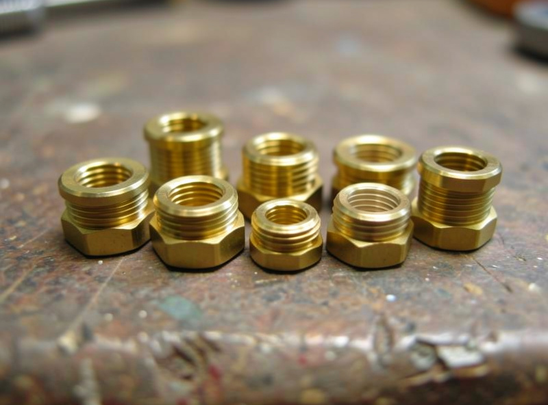
The job needs a temperature-controlled soldering iron and the right tip. A bare conical tip works but tends to push plastic up the sides; dedicated insert tips that match the insert’s internal thread seat it dead square and release cleanly. I keep a cheap set of heat-set insert tips for my iron and reach for them constantly. For the inserts themselves, a mixed brass insert assortment in M2 through M5 covers almost every functional part. As an Amazon Associate I earn from qualifying purchases.
Beyond that you want a flat surface to press against, and ideally a small square or the flat of the part to check the insert is going in vertically. That is the whole kit. A press or a jig helps for production runs, but for normal workshop work a steady hand and a flat reference are plenty.
Step by Step: Seating an Insert
Set the iron to the right temperature for your material — for PLA around 200–220°C, for PETG and ABS a little hotter, roughly 230–250°C, so the plastic flows without scorching. Place the insert on the hole, tapered or knurled end down, so it sits balanced on the opening. Bring the heated tip into the insert’s bore and let the brass come up to temperature for a second or two before applying any pressure.
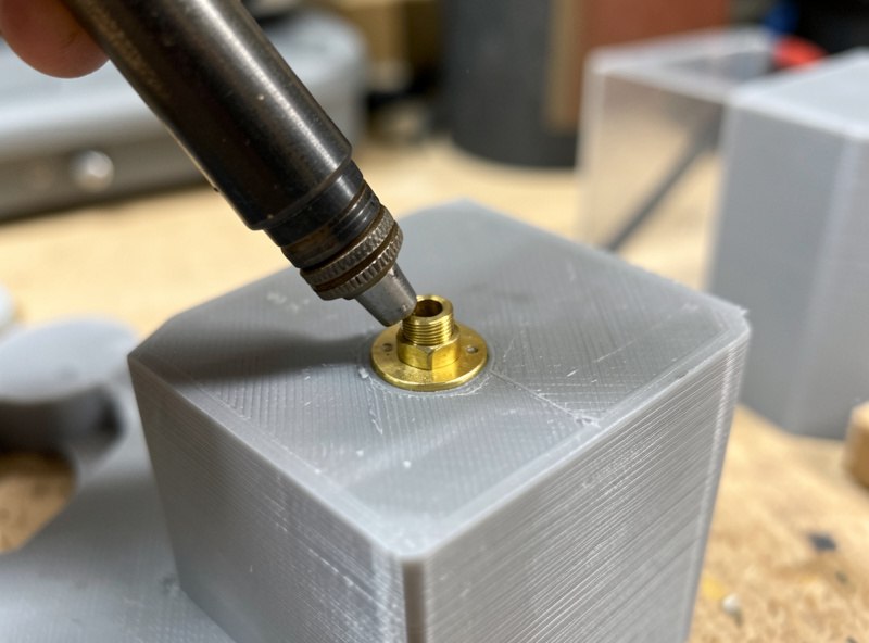
Once the surrounding plastic softens, press the insert straight down slowly and steadily until its top sits flush with or just below the part surface. Keep it vertical — this is where the flat reference helps. Remove the iron and, before the plastic resolidifies, you have a moment to nudge a slightly tilted insert square. Let it cool completely before threading a screw; brass holds heat and the plastic needs to set around the knurls. A small ring of squeezed-out plastic around the rim is normal and can be trimmed.
Common Mistakes and How to Avoid Them
The most common failure is going too fast: pushing before the plastic has softened forces the insert in crooked or cracks the boss. Let the heat do the work. The second is the wrong hole size — an insert that drops in with no resistance had too big a hole, and one that won’t start had too small a hole. The third is too high a temperature, which scorches and bubbles the plastic and can leave the insert loose once that degraded material cools.
A tilted insert is the other frequent issue, and it matters because a crooked thread cross-threads the screw. Seating against a flat surface and checking vertical before the plastic sets fixes it. If an insert does end up loose or proud, you can usually reheat it, push it the rest of the way or add a drop of plastic, and reseat. Treat the first few as practice prints — the skill transfers permanently after a handful.
Blind Holes, Through Holes, and Insert Direction
Where the insert sits in the part changes how you design the hole. A blind hole — closed at the bottom — needs to be a little deeper than the insert plus a small relief pocket, so displaced plastic has somewhere to flow instead of pushing back and doming the insert proud. A through hole is more forgiving because plastic and air escape the far side, but you still want the boss thick enough that the insert does not split it.
Insert direction matters for load. Most tapered inserts go in from the side the screw enters, so the wide knurled end ends up below the surface where pull-out forces act against the most brass. If a joint will see heavy pull-out, orient the part so the insert axis runs along the print’s strong in-plane direction where possible, rather than straight up the layer stack. This is the layer-anisotropy effect detailed in Protolabs Network’s FDM design guidelines. It is a small refinement, but on a fixture that takes real load it is the difference between an insert that holds and a boss that peels apart at a layer line.
Where Heat-Set Inserts Earn Their Keep
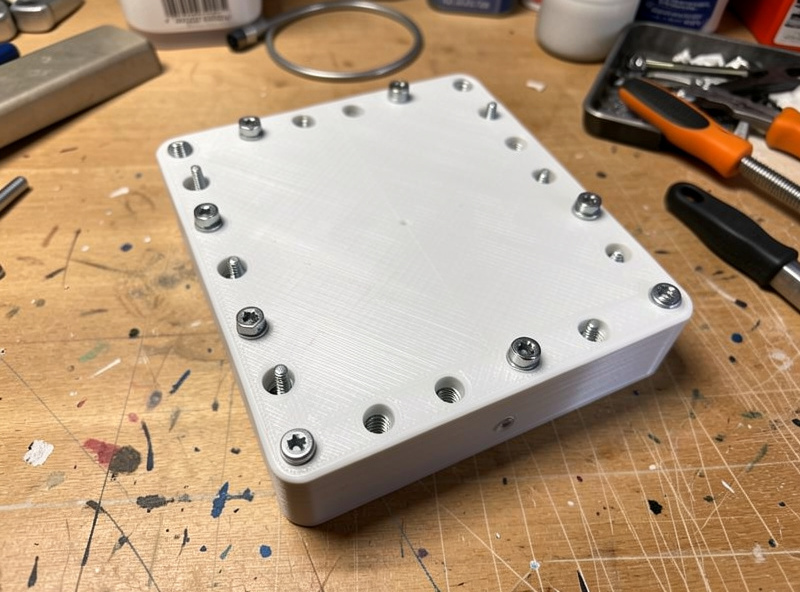
Any part that opens and closes is a candidate. On my bench that means enclosure lids, the sensor mounts I print for smart-home gear, battery boxes, and welder fixtures that get reconfigured. They also let you build proper bolted assemblies — two printed parts pulled tight with a machine screw and insert hold far better than glue or self-tappers, and they come apart cleanly for repair. Pair them with the other functional joining methods — snap and press fits for tool-free assembly, and good tolerances for parts that mate — and you can build genuinely serviceable machines from printed parts. Choosing a tough material helps too; PETG and ABS hold inserts better than brittle PLA, as the filament guide explains.
Frequently Asked Questions
What size hole do I need for a heat-set insert?
Model the hole slightly smaller than the insert outer diameter so there is plastic to grip. As a starting point: 3.0 mm for M2, 3.8 mm for M3, 5.3 mm for M4, and 6.1 mm for M5. Check your insert spec and add a boss around the hole.
What temperature should I set my soldering iron for heat-set inserts?
Match the plastic. Around 200 to 220 C works for PLA, and roughly 230 to 250 C for PETG and ABS so the plastic flows without scorching. Let the brass heat for a second or two before pressing so the surrounding plastic softens evenly.
Can you put heat-set inserts in PLA?
Yes, PLA takes inserts well at a lower iron temperature around 200 to 220 C. PETG and ABS hold them slightly better because they are tougher and less brittle, but PLA is perfectly serviceable for parts that are not under heavy repeated load.
Why is my heat-set insert going in crooked?
Usually too much pressure too soon, or seating without a flat reference. Let the plastic soften before pressing, push straight down slowly, and check the insert is vertical against a flat surface. You have a moment before the plastic sets to nudge a tilted insert square.
Do I need special tips for my soldering iron?
Not strictly, but dedicated insert tips that match the insert thread seat it square and release cleanly, where a bare conical tip tends to push plastic up the sides. A cheap set of insert tips makes the job faster and far more consistent.
How much weight can a heat-set insert hold?
Far more than a screw in plastic, because the knurled brass anchors into the surrounding material and resists both pull-out and tightening torque. With an adequate boss around it, an insert easily handles normal fastening loads and dozens of assembly cycles without stripping.