Design for strength in 3D printing starts in CAD, not the slicer. The strongest part is one shaped to match how FDM actually builds — loads carried within layers, corners filleted instead of squared, and material added as ribs rather than bulk. Get the geometry right and a part can survive loads that would shatter a thicker, heavier version designed without the process in mind.
Most “weak print” problems I see are really design problems wearing a slicer-settings costume. People crank infill and add walls to rescue a shape that was always going to fail at a sharp internal corner or a hole drilled straight through a thin wall. The fixes that matter most cost nothing but design time. This is the companion to choosing the strongest infill and orientation — that guide handles the slicer; this one handles the model.
Design With the Layer Lines, Not Against Them
Because FDM is weak between layers, the first design move is to imagine how the finished part will sit on the bed and route the loads accordingly. If a feature is going to be pulled, sheared, or bent, design it so the print orientation puts solid plastic across that load rather than a layer bond. Sometimes that means changing the part’s shape so a strong orientation is even possible — splitting a part in two and joining it, or moving a mounting tab to a face that prints flat.
This is where designing and orienting blur together. I sketch the load path first, decide the build orientation that keeps it in-plane, then shape the rest of the part around that decision. A part designed orientation-first is dramatically stronger than the same idea modelled in a vacuum and oriented as an afterthought. It is the single highest-leverage habit in the whole functional printing workflow.
Fillet Every Internal Corner
Sharp internal corners are where parts crack. A square inside corner concentrates stress at a single point, and on a printed part that point usually lines up with a layer boundary — a crack waiting to happen. Adding a fillet, even a small one, spreads that stress over a curve and can dramatically raise the load the corner survives. It is the cheapest strength upgrade in CAD and the one beginners skip most.
The rule I follow: fillet every internal corner that carries load, and make the radius as large as the design allows. Where a wall meets a base, where a tab joins a body, where a slot ends — all of these get a radius. External corners matter less for strength but a small chamfer there helps the print and tames elephant’s foot. You do not need to calculate the exact radius; bigger is better up to the point it interferes with function. Protolabs Network’s key design considerations cover fillets, wall thickness, and the other features that decide whether a printed part holds.
Use Ribs and Gussets Instead of Thick Walls
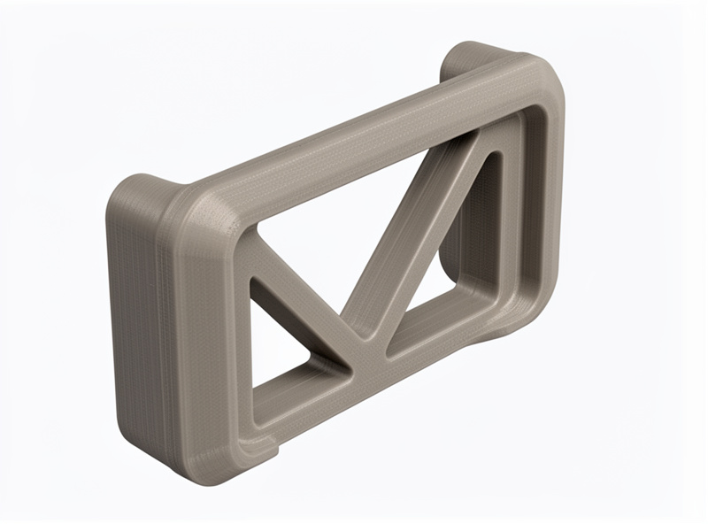
When a part flexes too much, the instinct is to make it thicker. That works but it is wasteful and slow, and thick solid sections can warp and trap stress. The efficient answer is ribs: thin reinforcing walls that add stiffness exactly where bending happens, using a fraction of the material. A gusset — a triangular rib bracing a right angle — turns a floppy 90-degree joint into a stiff one almost for free.
I size ribs at roughly the wall thickness of the part, tall enough to do the job but not so tall they become unsupported and wobbly. Several modest ribs beat one massive one. This mirrors how injection-moulded parts are designed for the same reason — stiffness from geometry, not mass. Protolabs Network’s FDM design guidelines show the rib proportions that print cleanly without wobbling. The result prints faster, uses less filament, and resists bending better than a bulky equivalent. It pairs directly with the wall-and-orientation logic in the strength stack.
Reinforce Holes, Bosses, and Fasteners
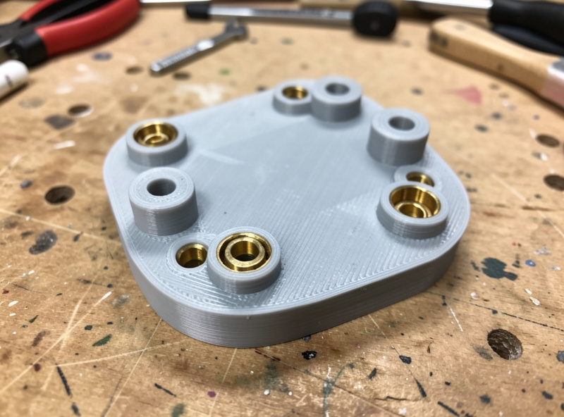
Holes are stress concentrators and thin walls around them split easily. Add a boss — a raised cylindrical reinforcement — around any hole that takes a fastener or a load, so there is meaningful material around it rather than a hole punched through a thin face. Where a screw goes, plan for the fastener strategy at design time: model the hole for a brass heat-set insert rather than expecting threads to hold in raw plastic. My heat-set inserts guide covers the exact hole diameters.
The same thinking applies to snap fits and press fits: a snap clip needs a cantilever long and thin enough to flex without cracking, and a press-fit boss needs enough wall around it to grip without splitting. Designing those features with the right clearances is its own skill — I cover the geometry in the snap fits and press fits guide and the dimensional side in the tolerances guide. Plan the joint, then design the strength around it.
Wall Thickness and Feature Size That Print Well
A strong design also respects what the nozzle can build. Walls thinner than two extrusion widths print as weak single lines; I design load-bearing walls at a minimum of two to three perimeters’ worth of thickness so the slicer fills them solidly. Very thin tall features become fragile and wobble during printing, so I either thicken them or add a supporting rib. Bridging spans and overhangs beyond about 45 degrees need either redesign or support, and unsupported plastic is always weaker.
Designing to the process means thinking in extrusion widths, not arbitrary millimetres. A wall that is an exact multiple of your line width fills cleanly with no thin gap; an awkward thickness leaves a weak underfilled core. It is a small habit that makes the slicer’s job — and the part — stronger. When a feature genuinely cannot be made strong enough in plastic, that is the signal to move it to metal; my print-to-CNC hybrid workflow covers when to make that jump.
A Worked Example: Redesigning a Weak Bracket
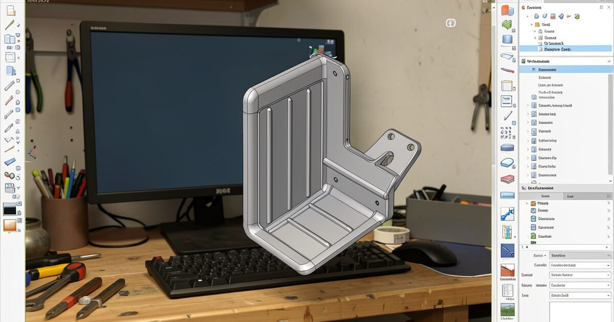
Here is the process on a real part from my bench. I needed an L-bracket to hang a small pump inside a hydroponic cabinet — a few kilos of load, occasional knocks. The first version was the obvious one: a flat L with a hole in each arm, printed upright because that looked tidy. It cracked at the inside corner the first time the pump swung against it. Classic failure: sharp internal corner, load peeling a layer bond, holes punched through thin arms.
The redesign fixed all three in CAD. I added a generous fillet at the inside corner and a triangular gusset bracing the angle, so the joint stopped flexing. I thickened the arms around the holes into raised bosses sized for heat-set inserts, so the fasteners pull on metal threads instead of plastic. And I reoriented the print so the bracket lies on its back, putting the gusset and corner in-plane where the layers run with the load. Same footprint, barely more filament, and it has carried the pump for months without complaint.
Nothing in that redesign was exotic — a fillet, a gusset, two bosses, and a smarter orientation. That is the whole discipline: small geometry changes that match how the part is built and loaded. The slicer settings on the second version were almost identical to the first; the strength came from the model.
Material and Print Settings Finish the Job
Good geometry sets the ceiling; material and settings decide how close you get to it. PETG is my functional default for its toughness and layer adhesion; ABS and ASA handle heat and outdoor exposure, and carbon-fibre blends add stiffness for parts that must not flex. Whatever the material, layer adhesion depends on printing hot enough and dry enough — a perfectly designed part still snaps at the layer line if the filament was wet. See the filament guide for matching material to the job.
Then the part comes back to the slicer for the strength stack: orient for the load, run four to six walls, set sensible infill, drop layer height on critical parts. Design and print settings are two halves of the same problem — neither rescues a failure in the other. The strongest parts I make are the ones where the CAD was shaped for the process and the slicer was set to match. A reliable machine ties it together; my Prusa MK4S is the benchmark I design around.
Frequently Asked Questions
How do I design a 3D printed part to be stronger?
Design for the process: route loads within the print layers, fillet internal corners, add ribs and gussets instead of thick walls, reinforce holes with bosses, and plan for heat-set inserts where screws go. Geometry sets the strength ceiling before any slicer setting.
Why do fillets make 3D printed parts stronger?
Sharp internal corners concentrate stress at a single point, which on a printed part often coincides with a layer boundary and cracks. A fillet spreads that stress over a curve, raising the load the corner can survive. Make the radius as large as the design allows.
Are ribs better than thick walls for stiffness?
Usually yes. Ribs add stiffness exactly where bending occurs using a fraction of the material, while thick solid sections waste filament, print slowly, and can warp. Several modest ribs sized near the wall thickness beat one bulky section for both strength and print quality.
How thick should walls be for a strong 3D print?
Design load-bearing walls at least two to three extrusion widths thick so the slicer fills them solidly. Walls thinner than two perimeters print as weak single lines. Designing thickness as a multiple of your line width avoids a weak underfilled core.
Should I design holes for screws or for heat-set inserts?
For anything that gets disassembled, design holes for brass heat-set inserts rather than screws into plastic, which strip after a few cycles. Add a boss around the hole for material to grip, and size the hole to the insert outer knurl diameter for a clean, square seat.