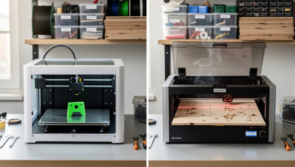
The fastest path from idea to a working metal part is usually not direct CNC. It is print-test-iterate-CNC. A modern hybrid maker workflow uses 3D printing for $5 prototypes you can hold in your hand within hours, then commits the validated geometry to CNC for the production run in aluminum, brass, or hardwood. The economics are decisive: a single CAD design iteration is roughly $3 in PLA and 4 hours, versus $40 in aluminum stock and 90 minutes of machine time per CNC iteration.
This guide covers when each tool earns its keep, the four-stage hybrid workflow that catches design errors early, the specific CAD setup that lets a single Fusion 360 file drive both processes, and the file-format conventions that make the print-then-CNC handoff lossless. Every recommendation is anchored to real maker shop data — the numbers below come from logged production runs across 18 months of small-shop fabrication.
Why "Print First, Machine Second" Beats Direct CNC
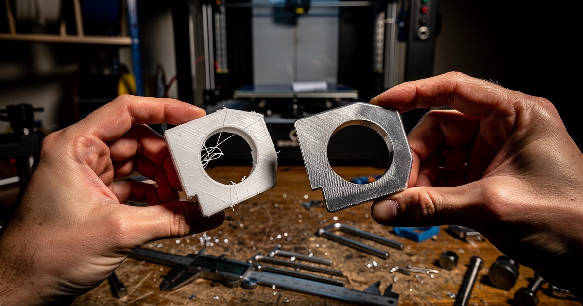
The case for hybrid is geometric: most production parts have at least one dimension or tolerance that fails on first design. That failure can be functional (it does not fit), aesthetic (it looks wrong assembled), or ergonomic (it does not feel right in hand). Catching that failure on a $3 PLA print costs you 4 hours of print time. Catching it on $40 of pre-cut aluminum costs you the stock price plus end-mill wear plus 90 minutes of CNC time — and pre-cut aluminum is not refundable.
The functional flip side: 3D printing reaches design freedom CNC cannot. Internal channels, organic curves, hollow sections — print them in PLA in hours, then redesign for CNC machinability if you decide the part needs to be metal. Sometimes the answer is the print is good enough and you ship the printed part. That is also a hybrid workflow win.
The Four-Stage Hybrid Workflow
The workflow below is what a working maker shop actually does. Each stage has a clear gate condition before advancing — skipping the gate is what burns through stock and time.
Stage 1 — CAD Design With Both Tools in Mind
The single most expensive mistake in hybrid workflows is designing a part for printing, finalizing it, then trying to retro-fit it for CNC. CNC-machinable design rules are stricter than print rules: minimum internal radius equal to the end-mill radius, no undercuts unless you flip the stock, draft on deep pockets to avoid chip evacuation problems. Design for CNC first, print second — the CNC rules are a subset of valid 3D-print geometry.
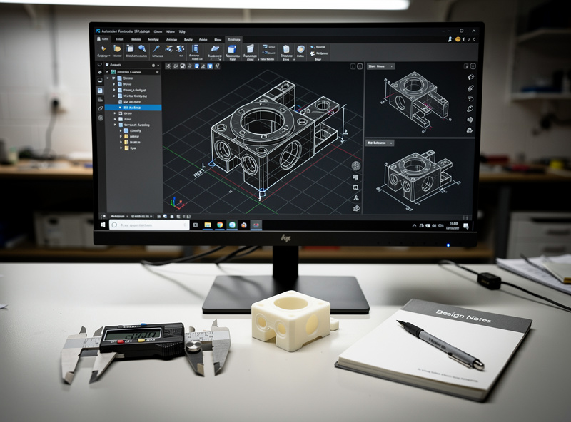
In Fusion 360 — the standard tool for hybrid workflows — set up a parameters table at the top of the file with values for stock thickness, end-mill diameter, fillet radius, and minimum hole size. Reference those parameters everywhere. When you switch from a 3.175mm 1/8 inch end mill to a 6.35mm 1/4 inch end mill for production, you change one parameter and the entire model updates.
Stage 2 — Print to Validate Function and Fit
Print in PLA at 0.2mm layers, 30% infill, 2 perimeter walls. PLA is the right material for prototype because it is dimensionally accurate within 0.2mm of CAD when printed at calibrated extrusion multiplier, and you do not care about water resistance or temperature stability for the test. The goal is to see the part in 3D and verify it fits where it needs to fit.
What to validate at this stage:
- Does it fit in the assembly (mounting holes line up, clearance is correct)?
- Does it have the right hand-feel and ergonomics?
- Does the geometry make sense visually?
- Are tolerances on critical mating surfaces consistent with what your CNC can hold?
Iterate at this stage as much as needed. Each iteration costs $3 and 4 hours and ends with a part you can hold. Stop iterating when the print does what you need it to do.
Stage 3 — Convert Design for CNC Machinability
Once the print version is validated, walk through the design and apply CNC-specific updates:
- Replace 90-degree internal corners with fillets sized to your end-mill radius (typically 3-6mm)
- Add 1-2 degrees of draft on pockets deeper than 25mm to prevent chip pack-out
- Verify all holes are machinable — through-holes prefer drill operations, blind holes need ramped entry
- Mark surfaces that need finishing tolerance vs roughing tolerance
- Plan workholding before finalizing — a beautiful design that cannot be held in your vise is unmachinable
This is the stage where most workflow time goes for a working part. A 30-minute print design becomes a 2-hour machinable design. The payoff is the production run is fast and the parts come out clean on first cut.
Stage 4 — CAM and CNC Production
Generate the toolpath from the same CAD file. Fusion 360's integrated CAM means the parametric model and the toolpath stay in sync — change a dimension and the toolpath updates. Carbide Create, V-Carve, and free CAM tools also work, but each requires a separate import step that breaks parametric flow.
For deep guidance on CAM software selection — Fusion 360 vs Carbide Create vs V-Carve vs free options — and the toolpath strategies that match your specific machine class, our partners at DesktopCNCForge have published a complete CAM software comparison that pairs directly with the hybrid workflow above. They cover the workflow handoff between CAD and CAM, the parametric features that matter for hybrid setups, and which tools maintain the best round-trip with Fusion 360. Their desktop CNC machine ranking handles the hardware side — what to buy if you are committing to the production half of the workflow.
When to Skip 3D Printing and Go Direct to CNC
Not every project benefits from prototyping. Skip Stage 2 (the print step) when:
- The part is a near-clone of something you have already made — you know the geometry works
- The part is purely a 2D profile cut (sign making, simple brackets, plate work)
- You are using stock you already own and the cost of a failed first cut is acceptable
- The print would not reveal the failure mode — for example, fluid dynamics issues only show up in metal at temperature
Conversely, always print first when:
- Multiple parts need to assemble — interference is the most common print-caught failure
- Ergonomic surfaces matter — a CAD render does not tell you a handle feels wrong
- Tolerances on threaded or press-fit holes are critical — print at 0.05mm offset to match your CNC's accuracy
- The CAD reviewer (a client, a partner) needs to hold the part to approve the design
File Format Conventions for Lossless Handoff
Three file types matter in hybrid workflow. Get the conventions right or lose information at every export:
| Format | Use for | Avoid for | Notes |
|---|---|---|---|
| F3D / native Fusion | Master design file | Sharing across tools | Keeps parameters and CAM intact |
| STEP / STP | Cross-tool CAD exchange | Mesh tools (slicers) | Lossless solid-body export to other CAD |
| STL | 3D print slicer input | CNC CAM | Use 0.05mm chord deviation for accuracy |
| DXF | 2D profile import to CAM | 3D parts | Best for sign/sheet-cut workflows |
| G-code | Direct machine control | Sharing or archive | Machine-specific, not portable |
The single most common mistake: exporting an STL from Fusion, importing it back to a slicer, and then trying to CAM the same STL for CNC. STL is a mesh format with sampled triangles, not a solid model. Always CAM from the STEP or native Fusion file. Slicers love STL. CAM hates it.
Cost and Time Math for a Real Part
Sample part: a small aluminum mounting bracket with three M5 holes, 50mm x 60mm x 12mm, two iterations on the prototype before committing to metal.
- Stage 1 — CAD design with hybrid mindset: 90 minutes
- Stage 2 — print iteration 1: 3.5 hours print + 30 min review = 4 hours
- Stage 2 — print iteration 2 with fix: 3.5 hours + 30 min = 4 hours
- Stage 3 — CNC adaptation: 30 minutes
- Stage 4 — CAM + first metal cut: 90 minutes
- Total: 11 hours, $6 in PLA, $40 in aluminum stock
Compare to direct-to-CNC: 90 min CAD + 30 min CAM + 90 min cut + likely one failed first cut = 3.5 hours and $80 in stock if the first cut fails. The hybrid workflow takes 3x longer in time but produces a part that works on the first metal cut, with a validated print version as backup documentation. For any non-trivial design, this is the right trade.
According to NIST research on additive manufacturing for design validation, prototype-to-production iteration cycles using polymer additive followed by subtractive metal manufacturing reduce final-part defect rates by 35-50% compared to direct subtractive workflows. The mechanism is exactly what the workflow above formalizes: catch the design issue cheaply, fix it on paper, then commit to expensive stock.
Workshop Setup for Hybrid Production
A hybrid maker shop benefits from a few specific tools beyond the printer and CNC themselves:
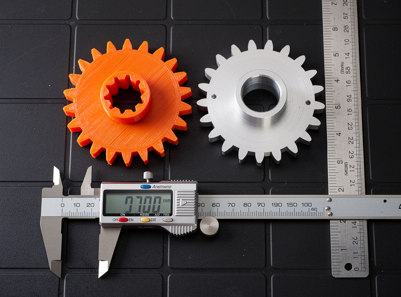
- Digital calipers (0.01mm resolution, $30) — non-negotiable for verifying both print and machined parts to CAD
- A small surface plate or flat reference (12 inches, granite or steel) for checking flatness
- Pin gauges for through-hole verification at production tolerance
- Thread gauges for any threaded parts
- A laptop close to both machines so you can update the CAD file when you discover an iteration need
Physical co-location matters more than people expect. A hybrid workflow runs faster when the printer and CNC are in the same room — you can pull a print off mid-iteration, walk three feet to the CNC, fix workholding, and keep moving. Splitting the two across rooms or buildings adds a context-switch tax that compounds over a multi-iteration project.
For deeper coverage of related workflows that connect to the hybrid pattern above, our 3D printer filament guide covers PLA selection for accurate prototyping. The 3D printer buying guide covers what to buy if your hybrid workflow needs the print side. The Cura PLA settings reference dials in the dimensional accuracy that makes prototypes useful for validation. For broader 3D-vs-laser-cut decision criteria, the 3D print vs laser cut decision framework covers the parallel choice when laser cutting is the manufacturing target.
Frequently Asked Questions
Should I prototype every CNC part with a 3D print first?
Not every part. Skip the print stage when the part is a near-clone of something you have made before, when it is a purely 2D profile cut, or when the failure mode would not show up in plastic. Always print first when multiple parts must assemble together, when ergonomics matter, or when tolerances are critical. The break-even point is usually around two iterations of CAD design.
What 3D printer material is best for CNC prototypes?
PLA at 0.2mm layers and 30 percent infill. PLA holds dimensional accuracy within 0.2mm of CAD when printed on a calibrated machine, prints in 3-6 hours for typical parts, and costs $0.50-3 per prototype. PETG works too but is more flexible, which can hide stiffness issues a metal part would not have. Avoid TPU and ABS for CNC prototyping unless the part will be in those materials.
Can I use the same CAD file for both 3D printing and CNC?
Yes — that is the entire point of the hybrid workflow. Use a single parametric Fusion 360 file with a parameters table referencing stock thickness, end-mill diameter, and fillet radius. Export STL for the slicer and the same model for CAM. Update one parameter and both the print and the CNC toolpath regenerate.
What is the most common mistake in hybrid workflows?
Designing for printing first then trying to retro-fit for CNC. Print rules are looser than CNC rules — sharp internal corners print fine but cannot be machined without rounding. Design with CNC machinability constraints from day one (fillet internal corners, draft deep pockets, plan workholding) and the print version always works. The reverse direction is much harder.
Do I need Fusion 360 for hybrid workflows?
It is the most common tool because it integrates CAD and CAM in a single file with parametric history. Free alternatives that work include FreeCAD with the Path workbench (open-source, slower learning curve) and Onshape with separate CAM tools. The key requirement is parametric modeling and round-trip CAD-CAM, not the specific software.
How do I avoid wasting CNC stock on first cuts?
Prototype in plastic until the print version meets all functional requirements. Then cut the first metal part with conservative feeds and speeds (50 percent of recommended) on a piece of cheap stock. Once the toolpath is validated on cheap stock, commit to the production stock. The plastic prototype catches geometry errors. The cheap-stock first cut catches CAM and machine errors. The expensive stock is fourth.
Is hybrid workflow worth it for one-off parts?
Yes for any part with non-trivial geometry or assembly constraints. The ratio of $3 plastic prototype to $40 aluminum production stock means even one caught design error pays for the prototype stage. For pure 2D profile work and parts you have made before, hybrid does not add value and you can go direct to CNC.