Print-in-place means printing a part with its moving joints already assembled — a hinge, gear train, or ball joint that articulates the moment it comes off the bed, with no assembly at all. The whole technique rests on one number: the clearance gap designed between the moving surfaces, typically around 0.3 to 0.4 mm on a well-tuned FDM machine, large enough that the surfaces never fuse but small enough that the joint is not sloppy.
This is one of the most genuinely impressive things desktop printing does, and it is also where a lot of prints fuse into a solid lump. The difference is almost always the gap, tuned to your specific printer’s real tolerance rather than a number from a video. I print a lot of print-in-place parts — hinged covers, articulating mounts, little mechanisms — and once you calibrate the gap for your machine it becomes reliable. This guide sits alongside living hinges in the functional printing workflow as the two ways to print moving parts.
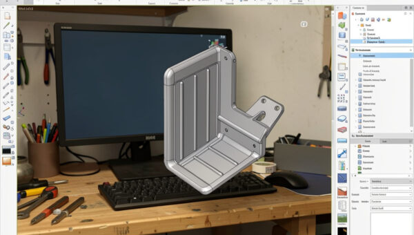
How Print-in-Place Works
The principle is simple: model the moving surfaces with a deliberate air gap between them so the slicer never bridges plastic from one part to the other. Because each surface prints as its own wall with a gap of unprinted space between, the parts stay separate even though they were printed in one job. A pin sits in a barrel, a gear meshes with its neighbour, a ball sits in a socket — all printed together, all free to move.
The catch is that FDM does not respect tiny gaps perfectly. Extrusion is slightly wider than commanded, the first layer squishes out, and walls can sag or string across a gap. If the designed clearance is smaller than the slop your printer actually produces, the surfaces touch, weld, and you get a solid part. So print-in-place is really a tolerance problem, and the fix is knowing your machine’s real-world clearance — the same skill covered in depth in my tolerances and clearances guide. Protolabs Network’s guide to dimensional accuracy explains why those small gaps drift on FDM in the first place.
The Clearance Gap: Your Most Important Number
The gap is everything. Too small and the joint fuses; too large and it rattles with play. On my machines a clearance around 0.3 mm is the reliable starting point for hinges and pins, with 0.4 mm for looser sliding joints and a touch less for snug ones. But that number is machine-specific — a tightly tuned printer with good first-layer control can go smaller, while a machine with extrusion slop needs more.
The honest way to find your number is to print a clearance test: a small part with several joints at different gaps, then see which one moves freely without being loose. Here are the starting clearances I use by joint type before testing on a new machine or material.
| Joint type | Starting clearance | Goal | Notes |
|---|---|---|---|
| Pin / barrel hinge | 0.30 mm | Free but no slop | Most common print-in-place joint |
| Sliding joint | 0.40 mm | Smooth travel | More gap for long contact faces |
| Ball and socket | 0.35 mm | Holds angle, moves by hand | Socket may need a relief slot |
| Meshing gears | 0.30 mm | Turn without binding | Tooth profile clearance critical |
PETG tends to need slightly more clearance than PLA because it strings and oozes more across gaps; flexible materials need more still. Always test the gap in the material you will print the final part in, because the value that works in PLA may fuse in PETG.
Orientation and First-Layer Squish
How the joint sits on the bed decides whether the gap survives. The first layer squishes wider than later layers, so any moving surface printed on or very near the bed gets a fatter first layer that can close the gap and weld the joint. Where possible, orient print-in-place joints so the moving interface is up off the bed, in the body of the print where layers are consistent, rather than down in the squished first few layers. Protolabs Network’s FDM design guidelines cover the orientation and first-layer effects that decide whether a gap survives.
A well-dialed first layer is non-negotiable for this work. If your first layer is over-squished, the gap at the bottom of a joint disappears and it fuses there even when the rest is free. Getting that right is part of general machine calibration — my calibration guide covers the first-layer and flow tuning that print-in-place depends on. A printer that nails its first layer and holds its extrusion width is one that prints these joints reliably; my Prusa MK4S is my benchmark precisely because it is consistent here.
Settings That Keep Joints Free
Stringing and oozing are the enemies of a clean gap, because stray plastic bridges the clearance and tacks the joint together. Good retraction tuning and a dry spool keep the gap clear — my PETG stringing fix is directly relevant if you print these in PETG. I also keep cooling adequate so plastic does not sag across the gap, and avoid printing the joint area too hot, which encourages ooze and sagging.
It helps to think about where the slicer will try to bridge. If a gap is narrow enough that the slicer decides to fill it, the joint fuses by design, not accident — so the modelled gap has to be comfortably larger than the slicer’s bridging threshold. Previewing the joint layers in PrusaSlicer or OrcaSlicer shows whether the gap is staying open or being filled. Thirty seconds in preview saves a fused four-hour print. After printing, the first movement often needs a gentle crack to free a joint that has lightly tacked — a small wiggle breaks any minor bridging and the joint runs free after.
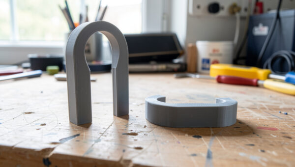
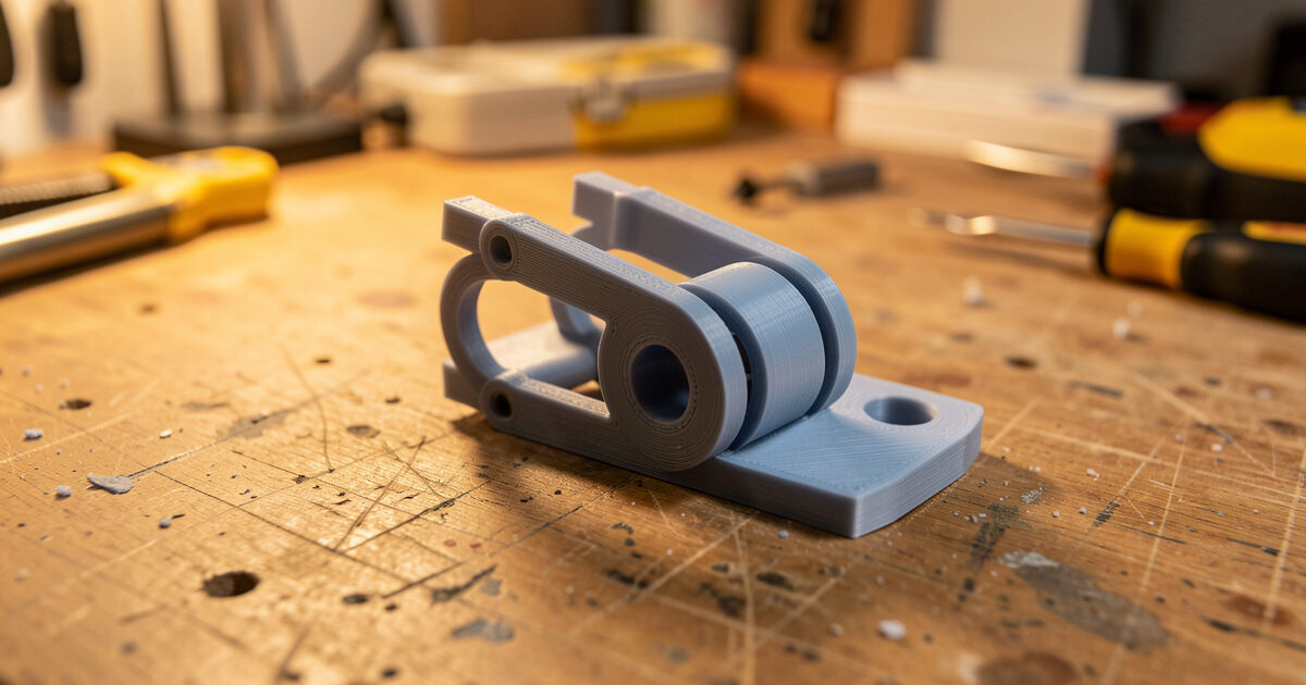
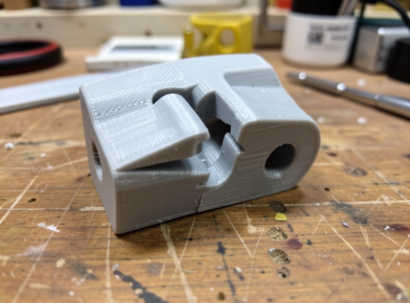
Designing a Simple Print-in-Place Pin Hinge
The pin-in-barrel hinge is the workhorse, and it is worth knowing how to model one because it is the basis for most print-in-place mechanisms. You model two interleaving sets of knuckles — like the leaves of a door hinge — with a continuous pin running through them. The pin is modelled as its own cylinder with the clearance gap all the way around it, so the barrel knuckles never touch the pin and it stays free to rotate.
The numbers that matter are the radial gap between pin and barrel, which I start at 0.3 mm, and the axial gap between adjacent knuckles, which wants a similar clearance so the leaves do not bind against each other side to side. Print the whole hinge flat with the pin axis horizontal, so the pin and barrels build as clean vertical-walled cylinders well off the bed rather than down in the squished first layers. That orientation is what makes the difference between a hinge that spins and one that comes out solid.
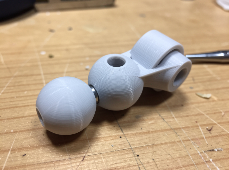
Once you have a pin hinge working on your machine, the same clearance logic scales to gear trains, chains, and ball joints — they are all just two surfaces held apart by a tuned gap. I keep one calibrated clearance value per material in my notes and reuse it across every print-in-place design, re-testing only when I change filament brand or machine. That single number, dialed in once, is what turns print-in-place from a gamble into a routine.
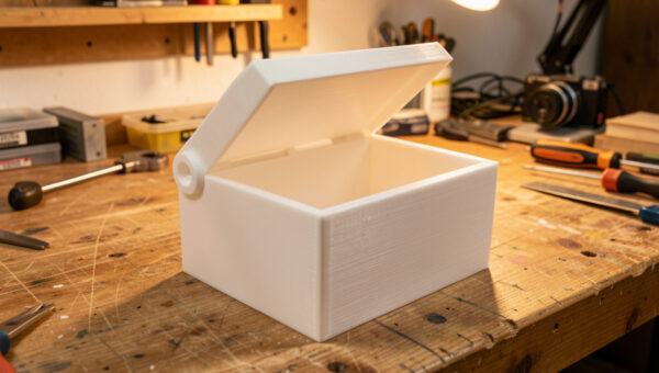
Print-in-Place vs Living Hinge vs Assembled
Print-in-place is not always the right answer. A living hinge is simpler and more elegant for a light folding lid, with no gap to tune — but it is a flex zone, not a true pivot, with limited bend angle and a little spring-back. A print-in-place pin hinge gives a real 360-degree pivot that carries more load and cycles harder, at the cost of needing the clearance dialed in. And sometimes printing two parts and joining them with a separate printed or metal pin beats both, when you want maximum strength or a precise bearing.
My rule: use a living hinge for light folding covers, print-in-place for true pivots and mechanisms where convenience matters, and a separate pin when the joint takes serious load. For closures that latch rather than pivot, a snap fit is the right tool. Matching the mechanism to the job is the same judgement that runs through all functional printing — the clever trick is only clever when it fits the duty.
Frequently Asked Questions
What clearance should I use for print-in-place joints?
Start around 0.3 mm for pins and hinges, 0.4 mm for sliding joints, and tune from there. The exact value depends on your printer and material, so print a clearance test with several gaps and pick the one that moves freely without slop. PETG usually needs slightly more than PLA.
Why did my print-in-place part fuse into one solid piece?
The clearance gap was smaller than your printer’s real-world slop, so the surfaces touched and welded. Over-squished first layers, stringing, and oozing all close the gap. Increase the modelled clearance, tune retraction, dry the filament, and keep moving joints up off the squished first layers.
Can you print moving parts in PETG?
Yes, but PETG strings and oozes more than PLA, so it needs slightly more clearance and good retraction tuning to keep the gap clear. Test the gap in PETG specifically, because a clearance that works in PLA may fuse in PETG.
How do I free a print-in-place joint after printing?
Most joints need a gentle first movement to break any minor tacking across the gap. Wiggle or flex the joint carefully and it usually frees and runs smoothly after. If it is solidly fused, the clearance was too small and the part needs reprinting with a larger gap.
Is print-in-place stronger than an assembled joint?
Usually not. A print-in-place joint trades some strength and precision for the convenience of zero assembly. For maximum load or a precise pivot, printing separate parts joined by a printed or metal pin is stronger. Print-in-place wins on convenience and part count, not raw strength.