LiFePO4 cells expand and contract by roughly 0.5mm per 100Ah during charge-discharge cycles, and an unconstrained prismatic cell swells unevenly enough to delaminate its internal layers within 300 cycles. 3D-printed PETG compression holders cost about $3 in filament per cell versus $15-25 for aluminum or steel fixtures, and they survive the 0-60°C operating range of LiFePO4 without deforming. The key design elements are a 0.8mm interference fit on cell faces, ventilation channels between cells for heat dissipation, and bus bar covers that prevent the kind of accidental short that turns a wrench into a welding electrode. For a 16S 48V pack, printing all the fixtures yourself saves roughly $300 compared to buying commercial compression plates and covers.
Why Compression Matters for Prismatic Cells
Prismatic LiFePO4 cells — the rectangular aluminum-cased cells you see in every DIY solar battery build — are not internally rigid. During charging, lithium ions intercalate into the cathode, expanding the internal layers. During discharge, the layers contract. The manufacturer data sheets for EVE, CATL, and CALB cells specify a compression range of 300-700 kgf at 50% SOC, and a cell cycled without compression loses 2-3% of its capacity per year versus roughly 0.5% when properly compressed. This is not theoretical — it is visible in the cell casing after 1-2 years of service as a slight bulge at the center of the broad face. The compression fixture’s job is to distribute this internal pressure evenly, preventing the center of the cell from expanding more than the edges, which concentrates mechanical stress at the internal tab connections.
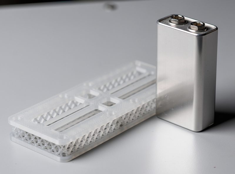
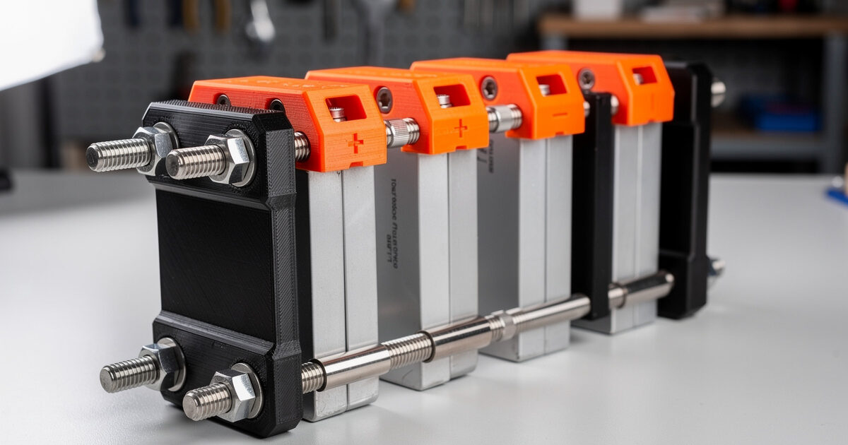
A PETG holder printed with 4 perimeters and 40% gyroid infill provides enough rigidity for a 280Ah cell without cracking. The design loads the compression force into the entire face of the cell via a flat contact surface, and the holder itself acts as a spacer — when you bolt through the four corners of the holder to the next cell in the stack, the bolts carry the tension and the holder transfers it as compression across the cell face.
Designing Cell Holders for Your Specific Cells
No two LiFePO4 cell models share the exact same dimensions, even within the same capacity class. An EVE LF280K is 173.7mm wide and 72mm thick, while a CATL 280Ah cell is 174mm wide and 71.5mm thick — that 0.5mm difference is a loose fit that eliminates compression if you use the wrong file. Before printing, measure your actual cells at 50% SOC with calipers, not a tape measure, and add the interference fit in the CAD model, not in the slicer. Fusion 360 or FreeCAD parametric models with the cell dimensions as user parameters let you re-generate the holder for a different cell in under two minutes just by changing the width, depth, and height values.
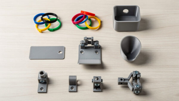
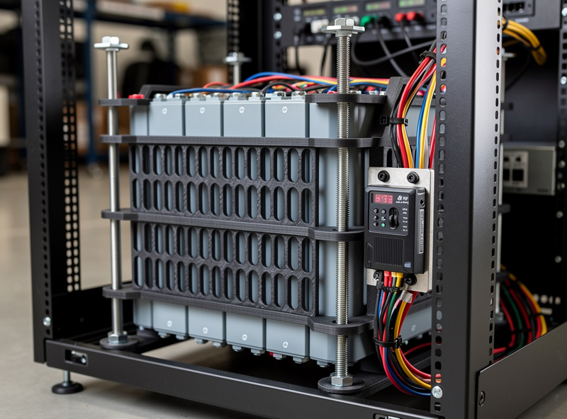
The corners of each holder need clearance for 6mm threaded rod or M6 bolts — that means 6.5mm holes through the four corners. The plates between cells should be 4mm thick minimum; thinner than that and PETG will creep under sustained compression load and lose tension within six months. Each cell-to-cell pair needs three printed parts: two compression faces (one on each cell) and one set of corner spacers that maintain a 3mm air gap. That air gap is not optional — cells at the center of a tightly-packed stack without airflow run 8-12°C hotter than end cells during a 0.5C charge, and LiFePO4 cycle life drops by roughly 50% for every 10°C increase in sustained operating temperature above 25°C.
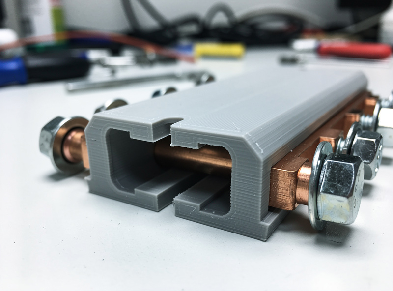
Bus Bar Covers: The $1 Safety Part Nobody Prints
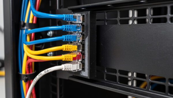
The most dangerous moment in any DIY battery build is not during assembly — it is six months later when you reach into the server rack to adjust a network cable near the exposed bus bars. A bus bar cover is a U-shaped channel that clips over the exposed nickel-plated copper connecting two adjacent cell terminals. It costs roughly $1 in PETG filament to print, fits snugly over M6 or M8 terminal studs, and prevents the short that turns a casual cable adjustment into a trip to the emergency room. Every cell-to-cell bus bar in a 16S configuration needs a cover — that is 17 covers for a standard 48V pack — and printing them yourself takes about 45 minutes for all 17 on a single build plate.
| Printed Part | Material | Print Time (per unit) | Filament Cost (per unit) | Commercial Equivalent Cost |
|---|---|---|---|---|
| Cell compression plate (280Ah) | PETG, 4 perimeters | 2 hours | $1.50 | $15-25 (aluminum) |
| Cell spacer / airflow channel | PETG, 3 perimeters | 30 minutes | $0.40 | $3-5 (nylon standoff) |
| Bus bar cover, U-channel | PETG, 3 perimeters | 3 minutes | $0.06 | $1-3 (ABS snap-on) |
| Terminal protective cap (M8) | TPU or PETG | 2 minutes | $0.04 | $0.50 |
| Balance lead holder / cable guide | PETG, 2 perimeters | 15 minutes | $0.15 | $2-4 |
| BMS mounting bracket | PETG, 4 perimeters | 1 hour | $0.80 | $8-15 (sheet metal) |
Print Settings That Actually Work
The slicer settings for battery fixtures differ from decorative prints in two ways that matter. First, print all compression plates and bus bar covers at 0.2mm layer height with the flat face down on the build plate — this orientation puts the layer lines perpendicular to the compression force, which is the strongest axis for FDM parts. Second, disable ironing on the cell-contact face. An ironed top surface is smooth but slightly domed at the edges due to excess material extrusion during the ironing pass, and a domed contact face concentrates compression force at the center of the cell rather than distributing it evenly. A non-ironed top surface with properly calibrated extrusion multiplier produces a flatter contact than an ironed one, even though it does not look as clean.
For PETG specifically, dry the filament before this print — PETG absorbs moisture from ambient air within 24-48 hours, and wet filament produces micro-voids in the part that act as crack initiation points under sustained compression. A filament dryer at 65°C for 4 hours before starting, and printing directly from the dryer if possible, eliminates this failure mode entirely. The difference between properly dried PETG and ambient-stored PETG in a compression fixture is the difference between a holder that maintains tension for 5,000 cycles and one that cracks at 300.
For the complete guide to building a LiFePO4 pack from cells to finished battery — including compression specs, bus bar torque values, and BMS wiring — see the DIY LiFePO4 battery bank build guide on BatteryStorageHQ, which covers the electrical and safety side that the printed fixtures here depend on.
Frequently Asked Questions
Can you 3D print battery cell holders for LiFePO4?
Yes. PETG with 4 perimeters and 40% gyroid infill provides enough rigidity for 280Ah prismatic cells. The holder maintains 300-700 kgf cell compression and survives 0-60C operating temperatures. Print with a 0.8mm interference fit against cell faces and include ventilation channels between cells for heat dissipation.
What filament is safe for battery holders?
PETG is the best choice for LiFePO4 holders because it handles 0-60C without softening and has good chemical resistance to any electrolyte that might vent. ABS works but warps on prints larger than 200mm. PLA is not suitable — it deforms above 50C, and a battery bank under heavy charge can reach 45C internally.
Why do LiFePO4 cells need compression?
Prismatic LiFePO4 cells expand roughly 0.5mm per 100Ah during charging. Without compression, uneven expansion concentrates stress at internal tab connections, causing 2-3% annual capacity loss versus 0.5% when properly compressed. Manufacturers specify 300-700 kgf of compression at 50% state of charge for optimal cycle life.
How much does a 3D-printed battery holder cost vs aluminum?
A PETG compression plate for a 280Ah cell costs approximately $1.50 in filament versus $15-25 for an aluminum equivalent. For a 16S 48V pack requiring 17 compression plates and bus bar covers, the total printed cost is roughly $35 versus $300-400 for aluminum and commercial covers.
Are 3D-printed bus bar covers safe?
Yes when printed in PETG with 3 perimeters. The cover is a non-conductive physical barrier that clips over bus bars to prevent accidental shorts from tools or cables. They are not a substitute for correct torque and proper terminal tightening — they are a safety overlay for working near live battery terminals.
What infill and perimeters should I use for battery holder parts?
Use 4 perimeters minimum for compression plates and BMS brackets — wall thickness provides more strength than infill percentage. Use 40% gyroid infill for its isotropic strength. Bus bar covers and terminal caps need only 3 perimeters and 15% infill. Do not reduce perimeters below 3 for any battery-related part.