Failure Is Part of the Learning Process
Every 3D printing operator, regardless of experience level, encounters failed prints. The difference between frustrated beginners and confident makers lies not in avoiding failures entirely but in understanding why prints fail and knowing systematic approaches to fixing them. This guide addresses the ten most common 3D printing failures you will encounter, explaining root causes, diagnostic techniques, and proven solutions that restore successful printing.
Each failure mode presented here includes identification characteristics, immediate corrective actions, and preventative measures that stop recurrence. Rather than presenting random troubleshooting tips, we organize solutions by symptom to enable rapid problem-solving when you encounter these issues. Bookmark this article—you will return to it frequently during your first months of printing.
Failure 1: Warping and Bed Adhesion Loss
Warping occurs when corners or edges of your print lift from the build plate during printing, creating curved bottoms instead of flat bases. In severe cases, complete detachment ruins the print entirely. This remains the most common failure mode for new operators and persistently frustrates even experienced users printing problematic materials.
Why Warping Happens
Thermoplastics contract as they cool. When upper layers cool and shrink while lower layers remain warm and adhered to the bed, internal stresses pull corners upward. Materials with high shrinkage rates (ABS, ASA, nylon, polycarbonate) suffer more than low-shrinkage materials (PLA, PETG). Large flat surfaces exacerbate the problem by providing more area for contraction forces to accumulate.
Immediate Solutions
Increase bed temperature by 10-15°C if not already at material maximum. Apply brim in slicer settings (5-10mm width) to increase surface area anchoring corners. Verify first layer squish is adequate—insufficient compression reduces adhesion. Clean the bed surface thoroughly with isopropyl alcohol to remove oils and residue. For severe cases, use raft instead of brim, though this adds post-processing work.
Long-Term Prevention
Print in enclosed chambers for temperature-sensitive materials. Consider upgrading to better bed surfaces like PEI or textured powder-coated steel. Use draft shields (slicer settings that print thin walls around the part) to block air currents. Reduce print speeds for first layers to improve adhesion. For large flat parts, consider splitting into multiple pieces to reduce per-part contraction forces.
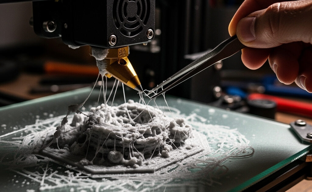
Failure 2: Stringing and Oozing
Stringing leaves thin threads of plastic connecting different parts of your print or hanging in open spaces. Oozing produces blobs and zits on outer surfaces, particularly at layer starts. Both issues stem from molten plastic dripping from the nozzle during travel moves between print sections.
Why Stringing Happens
When the nozzle travels between two points without printing, gravity and internal nozzle pressure cause molten plastic to drip. If retraction settings (pulling filament back before travel) are insufficient, plastic continues flowing during movement. High temperatures increase material flow and worsen stringing. Wet or degraded filament can also cause inconsistent extrusion leading to blobs.
Immediate Solutions
Enable combing in your slicer to force travel moves through infill areas rather than open space. Increase retraction distance by 0.5mm increments (for direct drive) or 1mm (for Bowden) until stringing reduces. Increase retraction speed slightly. Lower print temperature by 5-10°C to reduce material flow. Check filament dryness—bake wet filament at 50-60°C for 4-6 hours to remove moisture. For a more controlled solution, the best filament dry box guide compares dedicated dryers that maintain precise temperature and let you print straight from the box.
Long-Term Prevention
Calibrate retraction settings using dedicated stringing test prints for each material. Maintain filament in dry storage with desiccants, especially for hygroscopic materials like nylon and PETG. Consider upgrading to direct drive extrusion for materials that consistently string with Bowden systems. Enable coasting (stops extrusion slightly before end of print moves) in advanced slicer settings.
Failure 3: Layer Shifting
Layer shifting appears as abrupt horizontal offsets where subsequent layers print in wrong positions relative to previous layers. The result looks like the print was sliced horizontally and reassembled incorrectly. This mechanical failure indicates physical movement system problems.
Why Layer Shifting Happens
Stepper motors lose steps when mechanical resistance exceeds their torque capacity. Causes include loose belts allowing pulley slippage, mechanical obstructions blocking carriage movement, excessive print speeds or acceleration demanding more torque than motors provide, or insufficient stepper motor current limiting available power.
Immediate Solutions
Stop the print immediately upon noticing shifts—continuing wastes material on ruined parts. Check belt tension on affected axis; belts should produce a low musical note when plucked (approximately 100-120 Hz). Verify no loose screws, cable drag, or physical obstructions interfere with movement. Reduce print speed by 25% and acceleration by 30% in slicer settings. Check pulley set screws are tight on motor shafts.
Long-Term Prevention
Maintain proper belt tension through regular checks—loosening occurs over months of operation. Upgrade to wider belts or belt tensioners if frequent adjustments needed. Verify stepper driver current is properly calibrated (reference voltage setting). Reduce maximum acceleration and jerk settings in firmware to values your mechanical system can reliably handle. Consider linear rail upgrades replacing wheel systems for more precise movement.
Failure 4: Under-Extrusion and Gaps
Under-extrusion manifests as weak, porous layers, gaps between perimeter lines, missing infill, and parts that break easily along layer lines. The printer appears to print normally but deposits insufficient plastic to create solid structures.
Why Under-Extrusion Happens
Insufficient material flow results from partial nozzle clogs, incorrect extrusion multiplier settings, grinding filament at the extruder (preventing proper feeding), partial heat creep softening filament too early, or insufficient nozzle pressure due to excessive print speeds. Wet filament can also cause inconsistent extrusion as steam bubbles disrupt flow.
Immediate Solutions
Check extruder tension—filament should have light tooth marks but not be deeply gouged. Cold pull (atomic pull) the nozzle to clear partial clogs: heat to print temperature, manually feed filament, cool to 90°C, then pull firmly to extract debris. Verify extrusion multiplier in slicer is 1.0 or higher (increase by 5% increments if under-extrusion persists). Reduce print speed by 20% to allow proper flow. Check hot end cooling fan operates properly—failure causes heat creep.
Long-Term Prevention
Keep spare nozzles for replacement when cleaning fails. Use quality filament from reputable manufacturers—cheap filament often has inconsistent diameters causing flow issues. Maintain dry filament storage. Clean nozzles regularly using cold pull technique or occasional cleaning filament. Replace worn PTFE liners in hot ends that show degradation. Upgrade to all-metal hot ends for high-temperature printing to eliminate PTFE degradation issues.
Failure 5: Over-Extrusion and Blobs
Over-extrusion produces messy surfaces with excess material buildup, drooping features, loss of fine detail, and dimensional inaccuracy from plastic pushing beyond intended boundaries. Nozzle dragging through previous layers often accompanies severe over-extrusion.
Why Over-Extrusion Happens
Excessive flow results from extrusion multipliers set too high, incorrect filament diameter settings in slicer (1.75mm filament set as 1.60mm causes over-extrusion), slicer flow calculations assuming wrong nozzle diameter, or mechanical issues like loose extruder gears causing inconsistent feeding that averages to over-extrusion.
Immediate Solutions
Verify filament diameter setting in slicer matches your actual filament (usually 1.75mm or 2.85mm). Calibrate extrusion multiplier by printing a single-wall cube and measuring wall thickness—adjust multiplier until walls match nozzle diameter (typically 0.4mm). Check nozzle diameter in slicer settings matches physical nozzle size. Reduce flow rate by 5-10% in slicer until surfaces clean up.
Long-Term Prevention
Measure actual filament diameter at multiple points with calipers and enter average in slicer (cheap filament varies ±0.05mm). Calibrate e-steps (extruder steps per millimeter) in firmware to ensure extruder moves correct filament length when commanded. Maintain consistent nozzle sizes and update slicer profiles accordingly when changing nozzles.
Failure 6: Layer Separation and Splitting
Layer separation appears as visible gaps between layer lines or parts that split along layer boundaries when flexed. The print lacks structural integrity because layers failed to bond properly during printing.
Why Layer Separation Happens
Poor layer adhesion stems from insufficient print temperature (layers too cool to bond), excessive cooling fan speed (solidifying layers before next layer bonds), printing too fast (insufficient time/pressure for thermal fusion), or incorrect layer height settings creating insufficient overlap between layer beads.
Immediate Solutions
Increase print temperature by 10°C (stay within material safe range). Reduce cooling fan speed to 30-50% for materials like PETG and ABS that need layer heat retention. Reduce print speed by 20% to improve layer bonding time. Verify layer height is appropriate for nozzle diameter (generally 25-80% of nozzle width, so 0.1-0.32mm for 0.4mm nozzle).
Long-Term Prevention
Print temperature towers to identify optimal temperatures for each material. Use sufficient perimeters (3-4 walls) to create strong shells. Enable monotonic infill in advanced slicers to ensure consistent layer overlap patterns. Increase layer width slightly in slicer settings to improve layer-to-layer contact area. Avoid printing in drafty environments that accelerate cooling.
Failure 7: Support Failures and Poor Overhangs
Overhangs droop or sag, bridges fall, and supports detach or fail to support features properly. These related issues stem from unsupported sections exceeding printer capabilities.
Why Overhangs Fail
FDM printing builds on previous layers. Overhangs exceeding 45-60 degrees print in mid-air without support beneath, causing drooping. Bridges spanning gaps without support material sag under gravity during printing. Insufficient support generation in slicer leaves critical areas unsupported.
Immediate Solutions
Enable supports in slicer for overhangs exceeding 45 degrees (default threshold). Increase support density for small features or reduce support top distance for better contact. Orient parts in slicer to minimize overhangs—sometimes rotating 15 degrees eliminates support needs. Enable bridge detection in slicer for automatic bridge settings. Reduce layer height for overhang sections (adaptive layer height if slicer supports).
Long-Term Prevention
Design parts with 45-degree rule in mind—features visible from above should not exceed 45 degrees from vertical. Use chamfers and fillets instead of sharp overhangs. Consider splitting parts into multiple orientations for assembly rather than printing as single complex pieces. Upgrade cooling solutions (part cooling fans, duct designs) to improve overhang performance. Learn tree supports or organic supports for material-efficient support generation.
Failure 8: Heat Creep and Filament Jams
Heat creep causes filament to soften too high in the hot end, jamming the extruder. Symptoms include clicking extruder motors, grinding filament at the drive gear, and sudden print stops mid-way through previously successful prints.
Why Heat Creep Happens
Inadequate hot end cooling allows heat to travel upward past the heat break into the cold zone. All-metal hot ends are particularly susceptible. Blocked heat break cooling fins, failed cooling fans, or printing in warm ambient conditions exacerbate the issue. PLA, with its low glass transition temperature, jams more easily than higher-temperature materials.
Immediate Solutions
Check hot end cooling fan operation—fan should run continuously during printing. Clean dust from heat sink fins using compressed air. Verify heat break is properly tightened in heatsink with thermal paste at the interface. Reduce retraction distance—excessive retractions pull molten material into cold zone. Lower print temperature if possible within material limits.
Long-Term Prevention
Upgrade to larger or higher-quality hot end cooling fans. Use thermal paste between heat break and heat sink. Verify proper heat break installation depth—too shallow allows heat migration. Replace PTFE-lined hot ends with all-metal versions designed to prevent heat creep. Avoid printing PLA in warm ambient temperatures (over 30°C) without active chamber cooling.
Failure 9: Z-Axis Binding and Layer Height Inconsistency
Z-axis binding produces prints with inconsistent layer heights, visible banding patterns, or the nozzle physically dragging through previous layers. The mechanical Z-axis movement becomes irregular rather than smooth.
Why Z-Axis Binding Happens
Lead screws must move freely without binding against linear rails or frame components. Causes include misaligned lead screws bent during shipping or handling, insufficient lubrication creating friction, frame twist or assembly errors causing binding, or debris on lead screws creating obstacles.
Immediate Solutions
Manually move Z-axis through full range using control panel or by hand (with motors disabled) feeling for binding points. Lubricate lead screws with lithium grease or specialized 3D printer lubricant. Check lead screw couplers are properly aligned—misalignment causes wobbling. Verify Z-axis linear rails or rods move freely without binding against lead screws. For severe binding, disassemble and realign Z-axis components.
Long-Term Prevention
Maintain regular lead screw lubrication (every 100-200 hours printing). Keep lead screws clean and free of filament debris. Consider upgrading to dual Z-axis lead screws for larger printers to prevent cantilevered bed sagging. Anti-backlash nuts reduce Z-wobble artifacts on layers. Regularly check frame squareness and tighten frame bolts that may loosen from vibration.
Failure 10: Print Head Hits Previous Layers (Nozzle Drag)
The nozzle physically collides with previously printed layers, knocking parts loose, creating surface damage, or causing layer shifts. This often occurs progressively worse as print height increases.
Why Nozzle Drag Happens
Over-extrusion creates excess material height that the nozzle contacts on next layer. Incorrect Z-offset or bed leveling causes first layer too high, propagating height errors upward. Warping lifts corners into nozzle path. Model errors with overlapping geometry create physical collisions. Slicer bugs occasionally generate impossible toolpaths.
Immediate Solutions
Verify no over-extrusion by checking wall thickness matches nozzle diameter. Re-level bed ensuring proper first layer height. Check for warping and address root causes. Review sliced model in preview mode looking for impossible toolpaths or collision areas. Enable Z-hop (lifting nozzle during travel) in slicer settings to clear obstacles.
Long-Term Prevention
Maintain consistent extrusion calibration. Use proper first layer heights (typically 75-80% of layer height setting). Enable Z-hop for parts with many travel moves crossing printed areas. Verify models are manifold without overlapping geometry before slicing. For tall narrow parts, increase brim or raft width to prevent warping into nozzle path. Consider adjusting Z-offset slightly higher for tall prints to provide clearance margin.
Building Troubleshooting Confidence
Each failure you encounter and resolve builds diagnostic intuition. Eventually, you will recognize symptoms instantly and know which five settings to check first. This troubleshooting guide accelerates that learning curve by organizing solutions logically. Keep experimenting, keep documenting what works for your specific printer and materials, and remember that even professional operators encounter failed prints—they simply fix them faster.
With failure modes understood, the next article addresses the environment where printing occurs. Workspace setup dramatically affects print quality, safety, and printing enjoyment. Proper ventilation, storage solutions, and organizational systems transform 3D printing from a messy inconvenience into an efficient creative process.
]]>Prevent and Solve Problems
After mastering troubleshooting, learn post-processing techniques to improve the appearance of your prints. Or explore practical projects to apply your skills.