The Journey From Digital File to Physical Object
Creating successful 3D prints requires understanding the complete workflow from concept to finished part. Many beginners focus exclusively on printer operation while neglecting model preparation, slicing optimization, and post-print procedures that determine final quality. This comprehensive guide walks through every stage of the 3D printing pipeline, providing actionable techniques that separate amateur results from professional outcomes.
Whether you download models from online repositories, design your own in CAD software, or scan physical objects, the workflow remains fundamentally similar. Understanding each step’s purpose enables troubleshooting when prints fail and optimization when you demand maximum quality. By mastering this complete process, you transform from someone who occasionally gets lucky prints into a confident operator producing reliable results.
Stage 1: Acquiring 3D Models
Before printing anything, you need a digital model in a format your printer can interpret. Three primary methods exist for obtaining models: downloading from repositories, designing original parts, and 3D scanning physical objects.
Finding and Downloading Models
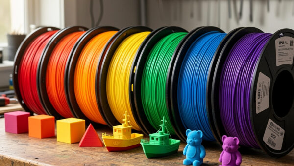
Online repositories provide millions of pre-made models for immediate printing. Thingiverse remains the largest repository with nearly five million free designs, though the site’s age shows in occasional upload issues and interface limitations. Printables (by Prusa Research) offers a more modern alternative with quality curation and contests that encourage excellent design. MyMiniFactory specializes in premium, tested models often created by professional designers. Cults3D operates as a marketplace with both free and paid models, typically at higher quality than purely free repositories.
When downloading models, verify file formats. STL (Standard Tessellation Language) is the universal format that all slicers accept. OBJ files include color and texture information but are less common for printing. 3MF (3D Manufacturing Format) represents the modern standard, containing more metadata including print settings, color information, and model integrity checks. Avoid proprietary formats requiring specific software to open.
Check model quality before printing. Downloaded files may contain manifold errors (holes in the mesh), non-manifold geometry (edges shared by more than two faces), or inverted normals that confuse slicers. Most slicers include mesh repair tools, but severely damaged models require fixing in Meshmixer, Blender, or Netfabb before printing successfully.
Designing Original Parts
Creating your own models unlocks the full potential of 3D printing. Computer-Aided Design (CAD) software ranges from beginner-friendly to professional-grade. Tinkercad provides a free, browser-based introduction using primitive shapes and boolean operations—perfect for learning fundamentals and creating simple functional parts. Fusion 360 (free for hobbyists) offers parametric modeling ideal for mechanical components with precise dimensions and assemblies. Blender, while primarily a 3D art package, includes excellent mesh modeling tools for organic shapes and sculpting. FreeCAD provides open-source parametric CAD without licensing costs.
Design for manufacturing from the start. Consider print orientation during design—overhangs over 45 degrees require supports, bridges longer than a few centimeters are risky, and wall thicknesses below your nozzle diameter print poorly. Use fillets on internal corners to reduce stress concentration. Design parts in multiple pieces if assembly yields better print orientation than printing as a single complex part.
Stage 2: Slicer Software Configuration
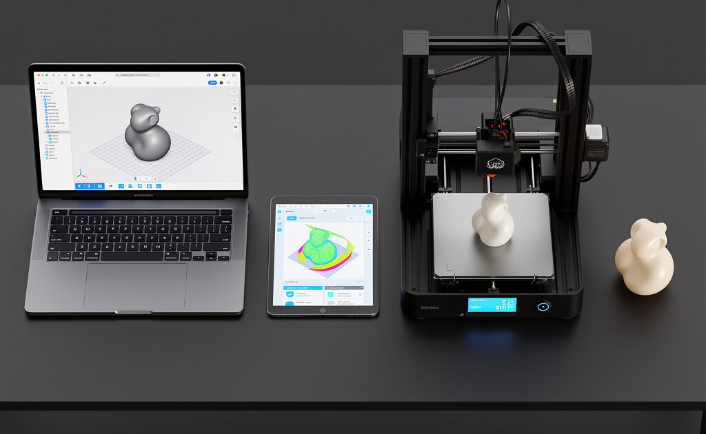
Slicer software transforms 3D models into G-code instructions your printer understands. Choosing and configuring the right slicer dramatically affects print quality, speed, and reliability.
Popular Slicer Options
Cura (free, Ultimaker) dominates the beginner market with automatic settings wizards and material profiles for hundreds of printers. The interface is approachable, though the sheer number of options can overwhelm newcomers. PrusaSlicer (free, Prusa Research) originated for Prusa printers but includes profiles for dozens of other machines. It offers superior print quality through organic supports and monotonic infill patterns. OrcaSlicer (free, fork of Bambu Studio) represents the current bleeding edge with built-in calibration tools, pressure advance tuning, and excellent default profiles. Bambu Studio works exclusively with Bambu Lab printers but demonstrates how integrated software-hardware ecosystems can simplify workflows.
Essential Slicer Settings
Layer height determines Z-axis resolution and print speed. Standard 0.2mm layers balance quality and speed for most prints. Fine 0.1-0.12mm layers produce smooth surfaces but take twice as long. Draft 0.3-0.4mm layers prioritize speed over appearance for functional parts. The optimal layer height depends on your nozzle diameter—generally 25-80% of nozzle width (0.1-0.32mm for 0.4mm nozzles).
Perimeters (shells) create the outer walls. Three perimeters provide good strength for most parts; two suffices for decorative items while structural parts benefit from four or more. Top and bottom layers should match perimeter count—three solid layers above and below infill prevent pillowing (gaps in solid surfaces). Infill density and pattern affect strength, weight, and print time. 15-20% infill suits most applications; structural parts may need 40-60%. Gyroid infill offers excellent strength-to-weight ratio and prints faster than grid patterns.
Print temperature directly affects layer bonding, surface finish, and dimensional accuracy. Start with manufacturer recommendations, then adjust based on results. Higher temperatures improve layer adhesion but increase stringing and reduce fine detail. Lower temperatures improve bridging and overhangs but risk weak layers and delamination. Print a temperature tower to identify the optimal range for each material on your specific printer.
Retraction settings prevent stringing by pulling filament back before travel moves. Direct drive extruders typically use 0.5-1.5mm retraction at 25-35mm/s. Bowden systems require longer retractions (4-6mm) at similar speeds. Excessive retraction causes jams and nozzle clogs; insufficient retraction leaves strings between features. Calibrate using retraction test prints.
Stage 3: Bed Preparation and First Layer Success
The first layer determines print success or failure more than any other factor. Poor adhesion causes warping, part detachment, and failed prints hours into the process. Mastering first layer technique separates experienced operators from frustrated beginners.
Bed Leveling and Tramming
Modern printers increasingly include automatic bed leveling (ABL) using inductive, capacitive, or physical probes. These systems map bed irregularities and compensate through software mesh bed leveling. Even with ABL, initial mechanical leveling should bring the bed reasonably flat. Manual bed leveling involves adjusting corner screws while moving the nozzle to each position and checking drag on a piece of paper.
First layer squish—the degree to which the nozzle compresses the first layer—dramatically affects adhesion. Too much squish spreads filament thinly with ridges on either side; too little creates rounded beads that fail to bond. The perfect first layer appears slightly flattened with no gaps between lines. Adjust Z-offset in 0.05mm increments until achieving this appearance.
Bed Surface Selection
PEI (polyetherimide) sheets have become the gold standard for bed surfaces, providing excellent adhesion when heated and easy release when cooled. Powder-coated PEI offers durability; smooth PEI produces glossy bottom surfaces. Glass beds (borosilicate or tempered) provide perfectly flat surfaces and work well with adhesives like glue stick, hairspray, or specialized 3D printing adhesives. BuildTak and similar textured surfaces offer good adhesion but require replacement as they wear. For specific materials, consider specialized surfaces—Garolite for nylon, polypropylene sheets for flexible filaments.
Bed Adhesion Techniques
Brims add single-layer material around the base of your print, increasing surface area and adhesion. Use brims for small-footprint parts, warping-prone materials like ABS, and tall narrow objects prone to tipping. Skirts print lines around the part without touching it, primarily purging the nozzle before starting the actual print. Rafts provide a sacrificial platform beneath the entire print, useful for problematic materials but adding post-processing work to remove.
First layer speed should be 50% of normal print speed or slower. Slow speeds allow proper squish and adhesion while giving the hot end time to deposit consistent material. First layer temperatures often run 5-10°C hotter than subsequent layers to improve bed bonding.
Stage 4: Monitoring Active Prints
Even properly prepared prints can fail due to environmental factors, mechanical issues, or slicer setting errors. Active monitoring enables catching problems early, potentially saving hours of wasted time and material.
First Layer Inspection
Watch the first 10-15 minutes obsessively. Verify the initial lines stick to the bed without lifting corners. Check for consistent extrusion without gaps or blobs. Confirm the nozzle maintains proper distance from the bed across all areas. Catching first layer problems early allows stopping and restarting rather than discovering a failed print hours later.
Common Mid-Print Failures
Layer shifting occurs when the print head or bed moves unexpectedly, creating offset layers. Causes include loose belts, insufficient stepper motor current, mechanical obstructions, or excessively high print speeds. Stringing leaves thin threads of plastic between travel moves, usually fixed by adjusting retraction settings or enabling combing (traveling through infill rather than open air). Heat creep causes jams when heat travels too far up the heat break, softening filament prematurely—often resolved by checking hot end cooling fans.
Remote Monitoring Solutions
OctoPrint (running on a Raspberry Pi connected to your printer) enables remote monitoring through web interfaces, webcam feeds, and mobile apps. It provides print control, file management, and plugin ecosystem including spaghetti detection (AI failure detection). Bambu Lab printers include built-in cameras and cloud monitoring. Klipper firmware with Mainsail or Fluidd interfaces offers similar capabilities with enhanced performance.
Stage 5: Removing and Cleaning Parts
Print completion marks the beginning of post-processing, not the end of the workflow. Proper removal and cleaning preserve part quality and prepare pieces for finishing or immediate use.
Safe Removal Techniques
Allow the bed to cool completely before removing parts—thermal contraction helps release prints from PEI and glass surfaces. For stubborn adhesion, use a thin, flexible scraper (metal or plastic) sliding under the print edge while gently flexing the bed surface if flexible. Never force prints off by pulling upward, which can damage both the part and build surface.
Remove supports carefully using flush cutters, needle-nose pliers, and craft knives. Angle cuts parallel to the surface to avoid gouging visible faces. For complex internal supports, consider dissolvable materials (PVA for dual-extrusion printers, HIPS for ABS prints) that eliminate manual removal entirely.
Initial Cleaning
Remove brim and skirt remnants using deburring tools or sandpaper. Clean stringing with a heat gun set to low temperature (melts and shrinks thin strings) or careful trimming. For functional parts with tight tolerances, verify dimensions using calipers and note deviations for future design adjustments.
Stage 6: Post-Processing and Finishing
Raw prints rarely represent final products. Post-processing transforms printed parts into professional components ready for assembly, painting, or functional use.
Sanding and Smoothing
FDM prints show visible layer lines that require sanding for smooth finishes. Start with 120-grit sandpaper removing high spots and obvious layer transitions. Progress through 220, 400, 600, and 800 grits for increasingly smooth surfaces. Wet sanding reduces dust and prevents melting from friction heat. For large flat areas, use sanding blocks maintaining flatness. Complex curves require careful hand-sanding following contours.
ABS and ASA parts respond to acetone vapor smoothing. Suspending parts in chambers with acetone-soaked paper towels creates vapor that dissolves surface layer lines, leaving glossy, injection-mold-quality finishes. This technique requires careful ventilation and safety precautions but produces professional results impossible through sanding alone.
Priming and Painting
Filler primer (automotive primer designed to fill scratches) levels remaining layer line evidence. Apply light coats, sanding between applications, until achieving uniform smoothness. Acrylic paints adhere well to properly prepared surfaces; spray painting provides even coverage while brush painting allows detail work. Clear coats protect finishes and add gloss or matte appearances as desired.
Assembly Techniques
Multi-part prints require joining. Super glue (cyanoacrylate) bonds PLA and ABS instantly with activator sprays. Epoxy provides stronger, more durable bonds suitable for structural applications. Acetone welding (for ABS/ASA) dissolves mating surfaces creating chemical bonds stronger than the material itself. Mechanical fasteners, threaded inserts (heat-set or press-fit), and dovetail joints designed into the model provide serviceable disassembly.
Workflow Optimization and Troubleshooting
Each print teaches lessons. Document settings that succeed and fail for each material and model type. Build a personal library of slicer profiles refined for your specific printer, materials, and common applications. Share knowledge with communities—3D printing advances through collective experience.
When prints fail, diagnose systematically. Check mechanical components (belt tension, bed leveling, nozzle condition) before blaming slicer settings. Verify filament quality and dryness — for PLA specifically, the does PLA need drying guide explains the humidity threshold and the quick test to determine whether a spool has absorbed enough moisture to affect prints. Review G-code preview in your slicer to identify obvious errors before printing. Keep a failure log noting symptoms, suspected causes, and solutions that resolved issues.
From Your First Print to Your Fiftieth
The workflow described here transforms overwhelming complexity into manageable stages. Your first prints will likely have imperfections; this is expected and educational. By your fiftieth print, bed leveling becomes automatic, slicing decisions become intuitive, and support removal feels routine. By your hundredth print, you will design specifically for the manufacturing process, creating parts that print reliably and function perfectly.
The learning curve is real but surmountable. Each failed print teaches more than successful ones when you analyze causes. Each successful print builds confidence and capability. This article provides the framework; your hands-on experience fills in the details specific to your equipment, environment, and applications.
With workflow mastery established, the next article addresses inevitable failures. Every operator encounters stringing, layer shifting, warping, and adhesion failures. Understanding these common problems and their solutions transforms frustration into quick corrections, maintaining momentum through the learning process.
]]>Master the Complete Process
With workflow understanding complete, set up your 3D printing workspace with proper ventilation and safety. Or learn to troubleshoot with our common failures guide.